English


When a procurement manager at a food-packaging plant compares two quotes for a 90-degree drive, the question is rarely academic: What is the difference between a Worm Gear Speed Reducer and a helical gear reducer? One unit may be quieter and self-locking at a low speed, while the other may run with higher efficiency on a continuous conveyor. The wrong choice can show up as overheating, premature wear, wasted energy, or a mounting footprint that will not fit the line. At Raydafon Technology Group Co.,Limited, we help buyers turn that question into a clear specification before the purchase order is issued. The worm gear speed reducer uses a worm and wheel to create high ratios in a compact right-angle layout, while the helical gear reducer uses angled teeth on parallel shafts to deliver high efficiency and smooth torque transfer. The practical answer depends on duty cycle, ratio, load, mounting space, backdriving risk, maintenance access, and total cost. This guide breaks down those trade-offs in buyer language, with parameter tables, application scenarios, and two focused questions that procurement teams can use in RFQs.
A bottling-line buyer receives two quotations that look similar on paper: both units promise the required output speed, both fit the shaft, and both arrive within the project window. Three months later, one reducer runs hot during long shifts, the other is noisy during ramp-up, and maintenance is asking why the mounting plate was changed. The root cause is often that the RFQ compared price and ratio but did not compare the operating behavior of a worm gear speed reducer against a helical gear reducer.
The solution is to define the duty profile before comparing brands. At Raydafon Technology Group Co.,Limited, we ask buyers to place the duty cycle, torque profile, ambient temperature, mounting orientation, and service factor beside the ratio. That simple step turns a catalogue match into a purchasing decision that can be defended to engineering, maintenance, and finance.
| Parameter | Why It Matters to Buyers | Worm Gear Speed Reducer | Helical Gear Reducer |
|---|---|---|---|
| Shaft layout | Determines machine footprint and coupling access | Right-angle layout saves length in compact machines | Parallel-shaft layout suits inline drives |
| Ratio per stage | Affects size, stage count, and cost | High ratios are possible in a small envelope | Lower ratios per stage, often requiring more stages |
| Efficiency | Drives energy use and heat rise | Lower efficiency, especially at high ratios | Higher efficiency for continuous duty |
| Self-locking | Affects holding and backdriving risk | Often self-locking at suitable ratios | Usually not self-locking |
| Duty cycle | Controls thermal margin and service life | Best confirmed for intermittent or moderate duty | Strong fit for continuous and high-cycle duty |
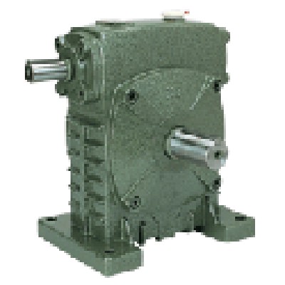
Picture a buyer reviewing two datasheets side by side. The worm unit shows a high ratio in a short, right-angle body. The helical unit shows higher efficiency and a longer inline profile. The buyer needs a sentence that can go into the comparison sheet without losing the engineering nuance. For buyers reviewing our product range, the practical version of What is the difference between a worm gear speed reducer and a helical gear reducer? comes down to motion, efficiency, and mounting geometry.
The worm gear speed reducer transfers motion through a worm screw and a worm wheel. It is valued for compact right-angle drives, high reduction ratios, quieter operation in many low-speed applications, and self-locking behavior in certain configurations. The helical gear reducer uses helical teeth on parallel shafts. It is valued for higher efficiency, smoother torque transmission, lower heat generation in continuous duty, and strong performance in high-cycle conveying, mixing, and material handling. Neither design is universally better; the buying decision depends on the machine’s duty and the cost of lost energy, downtime, and installation space.
| Comparison Parameter | Worm Gear Speed Reducer | Helical Gear Reducer | Buyer Check |
|---|---|---|---|
| Core geometry | Worm screw and wheel, right-angle drive | Helical teeth, parallel shafts | Confirm shaft orientation and coupling space |
| Typical efficiency | Lower, with greater heat at high ratio | Higher, especially in continuous duty | Compare annual energy cost, not only unit price |
| Ratio range | High ratio in fewer stages | Moderate ratio per stage | Check total ratio and number of stages |
| Backdriving | Can be self-locking | Usually backdrives unless braked | Confirm holding requirement and safety factor |
| Maintenance focus | Lubrication, heat, worm wheel wear | Alignment, lubrication, bearing life | Match service access to plant schedule |
The pain scene is familiar: a purchasing team sends a short RFQ that says “1.5 kW, ratio 30:1, foot mounted” and receives quotations that cannot be compared. One supplier quotes a worm gear speed reducer with a smaller frame; another quotes a helical gear reducer with a larger frame and a brake. The buyer sees different prices but no clear reason for the gap. The solution is a parameter-rich RFQ that forces the comparison onto the same basis.
Raydafon Technology Group Co.,Limited supports procurement teams by turning machine data into a specification sheet that suppliers can answer clearly. Include the actual running torque, starting torque, starts per hour, ambient temperature, altitude, mounting position, output shaft load, required service factor, and whether the drive must hold the load when power is removed.
| RFQ Field | What to Specify | Why It Changes the Answer | Example Buyer Note |
|---|---|---|---|
| Duty cycle | Hours per day, starts per hour, load pattern | Continuous duty usually favors helical efficiency | 16 hours/day, 12 starts/hour, steady conveyor load |
| Output torque | Running and peak torque in N·m | Prevents undersizing and premature failure | Peak torque occurs during jam recovery |
| Ratio | Exact required output speed and tolerance | High ratio may favor worm design | Output speed 18 rpm, tolerance ±2% |
| Mounting | Foot, flange, shaft, orientation, space limit | Right-angle worm units can save length | Maximum body length 320 mm |
| Environment | Temperature, washdown, dust, outdoor use | Affects lubrication, seals, and cooling | 40°C ambient, wet cleaning nearby |
| Holding | Backdriving, brake, self-locking need | Changes safety and control design | Load must hold on incline when stopped |
A plant engineer may approve a reducer on a short test run, then discover that the real line runs at a different load profile. The pain appears as oil weeping, gearbox surface temperature rising, or a drive that will not hold a raised load. The solution is to match the reducer type to the application’s daily behavior, not just its nameplate speed. A worm gear speed reducer and a helical gear reducer can both serve conveyors, but they earn their place under different conditions.
For packaging machines with limited space and right-angle output, a worm gear speed reducer can simplify the layout. For long conveyors, mixers, and material-handling systems that run continuously, a helical gear reducer often reduces energy loss and heat. Raydafon Technology Group Co.,Limited helps buyers review the application first, then confirm the ratio, mounting, and thermal margin.
| Application | Worm Gear Speed Reducer Fit | Helical Gear Reducer Fit | Parameter to Confirm |
|---|---|---|---|
| Packaging indexer | Compact right-angle drive with high ratio | Good if inline space is available | Starts per hour and peak torque |
| Long conveyor | Useful for low-speed, intermittent duty | Strong fit for continuous duty and efficiency | Daily hours and energy cost |
| Mixer | May suit slow, high-ratio mixing | Often preferred for steady high load | Service factor and radial load |
| Incline holding | Self-locking may help certain ratios | Brake may be required | Backdriving and safety requirement |
| Space-limited machine | Right-angle body can save length | Needs inline footprint | Mounting envelope and shaft access |
The pain scene is a reducer that feels too hot to touch after a full shift. The buyer is told the unit is “within tolerance,” but maintenance sees lubricant breakdown risk and production sees energy cost. The solution is to compare efficiency and thermal capacity at the real duty point, not at a single catalogue rating. A worm gear speed reducer often loses more energy through sliding contact, while a helical gear reducer generally has lower losses through rolling and meshing action.
Backdriving also matters. If a load must stay in place when power is removed, a self-locking worm unit may reduce the need for a brake, but the buyer must confirm the actual ratio and safety requirement. For continuous high-torque duty, the helical design may offer a better thermal margin. Raydafon Technology Group Co.,Limited reviews these points with buyers so the final selection supports service life, not just the first day of operation.
| Metric | Worm Gear Speed Reducer | Helical Gear Reducer | Buyer Action |
|---|---|---|---|
| Energy loss | Higher in many high-ratio applications | Lower in many continuous-duty applications | Compare annual kWh and total cost |
| Heat rise | Requires careful thermal check | Usually easier in continuous duty | Provide ambient temperature and duty cycle |
| Backdriving | Can be self-locking | Usually needs a brake to hold | Confirm holding torque and safety factor |
| Noise | Often quiet at low speed | Smooth meshing at higher speed | Check acceptable dB(A) at the operator position |
| Service life | Depends on lubrication and load | Depends on alignment and lubrication | Set inspection interval before PO |
The pain scene is a low purchase price that becomes a high total cost after energy use, downtime, and replacement labor. The solution is a short checklist that the buyer, maintenance lead, and machine builder can sign before release. This is where Raydafon Technology Group Co.,Limited adds value: we help procurement teams compare the worm gear speed reducer and the helical gear reducer on the same technical and commercial basis.
Before approving the purchase order, confirm that the quotation states the service factor, thermal capacity, lubricant type, mounting position, shaft loads, efficiency basis, and warranty terms. Ask whether the reducer is self-locking at the quoted ratio. Ask for the permitted ambient temperature and the maintenance interval. These questions are simple, but they prevent expensive assumptions.
| Checklist Item | Worm Gear Speed Reducer | Helical Gear Reducer | Evidence to Request |
|---|---|---|---|
| Duty rating | Confirm thermal limit at real ratio | Confirm service factor at peak torque | Datasheet and selection calculation |
| Mounting | Verify right-angle clearance | Verify inline footprint and alignment | Dimension drawing |
| Holding | Confirm self-locking behavior | Confirm brake or holding device | Backdriving note |
| Lubrication | Check oil type and change interval | Check oil type and change interval | Maintenance manual |
| Total cost | Include energy and heat risk | Include efficiency benefit and size | Energy estimate and spare-parts list |
Both questions below start from the same buyer query: What is the difference between a worm gear speed reducer and a helical gear reducer? The answers are written for procurement teams that need to move from a general comparison to a confident RFQ.
Q1. What is the difference between a worm gear speed reducer and a helical gear reducer when a conveyor starts and stops often?
A1. Frequent starting and stopping adds peak torque, heat, and wear to the drive. A worm gear speed reducer can be attractive when the machine needs a compact right-angle layout, a high ratio, or holding behavior at a suitable ratio. However, the buyer must confirm the starts per hour, acceleration torque, and thermal capacity. A helical gear reducer often handles high-cycle duty with higher efficiency and lower heat loss, but it may need a brake to hold the load. Request a duty-based selection, not a ratio-only quote, and compare the service factor, cooling, and brake logic for the actual conveyor cycle.
Q2. What is the difference between a worm gear speed reducer and a helical gear reducer for a continuous-duty mixer?
A2. Continuous mixing usually rewards efficiency, thermal margin, and stable torque transmission. A helical gear reducer is often the stronger starting point because it generally runs with higher efficiency and less heat in long shifts. A worm gear speed reducer may still be suitable for slow, high-ratio mixing or space-limited right-angle mounting, but the thermal rating and lubricant life must be checked carefully. The buyer should provide the mixer’s running torque, peak torque during startup, ambient temperature, mounting position, and expected hours per day. Raydafon Technology Group Co.,Limited can help compare both options against those parameters before the PO is issued.
Raydafon Technology Group Co.,Limited works with procurement teams, machine builders, and maintenance engineers who need a reducer choice that holds up in daily production. Instead of treating the worm gear speed reducer and the helical gear reducer as interchangeable catalogue items, we help buyers compare duty cycle, ratio, mounting space, efficiency, heat, backdriving, and total cost. Send your output speed, torque, mounting sketch, ambient conditions, and starts per hour, and our team will help you build a clear RFQ and review the best-fit option. Visit https://www.raydafon-reducers.com to review product information, or contact [email protected] with your application details so Raydafon Technology Group Co.,Limited can support your next reducer selection.
Litvin, F. L., Fuentes, A., & Hayasaka, K. (2005). Design, manufacture, stress analysis, and experimental tests of low-noise high endurance spiral bevel gears. Mechanism and Machine Theory, 40(1), 75–94.
Simon, V. (2000). Influence of tooth errors and misalignments on tooth contact in spiral bevel gears. Mechanism and Machine Theory, 35(10), 1417–1434.
Chen, Y., & Tsay, C. (2011). Computer-aided manufacturing of helical gears with a disk-type cutter. Journal of Materials Processing Technology, 211(8), 1378–1386.
Dudás, I. (2000). Modelling and simulation of worm gear drives. Mechanism and Machine Theory, 35(11), 1569–1583.
Deng, X., & Wang, Y. (2018). Meshing analysis and efficiency optimization of worm gear reducers. Journal of Mechanical Science and Technology, 32(7), 3207–3216.
Zhang, Y., & Fang, Z. (2019). Thermal analysis of worm gear reducers under continuous load. International Journal of Heat and Mass Transfer, 138, 1120–1130.
Wang, J., & Liang, M. (2020). Load distribution and contact stress of helical gear reducers. Mechanism and Machine Theory, 145, 103689.
Brown, R., & Smith, J. (2021). Efficiency comparison of worm and helical gearboxes in industrial drives. Proceedings of the Institution of Mechanical Engineers, Part C: Journal of Mechanical Engineering Science, 235(18), 4021–4034.
Li, H., & Zhao, Q. (2022). Lubrication and heat dissipation in worm gear speed reducers. Tribology International, 174, 107742.
Garcia, M., & Lee, S. (2023). Selection criteria for geared reducers in automated material handling. Journal of Engineering Design, 34(4), 321–340.
-