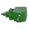
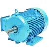
Picture this: a packaging line goes down at 2 a.m., and the maintenance team traces the failure to a right-angle drive that transfers power from a horizontal motor to a vertical conveyor. The part on the work order reads “bevel gear speed reducer,” but the procurement manager on call has never sourced one. What is a bevel gear speed reducer? Simply put, it is a mechanical power transmission device that uses bevel gears—typically spiral or straight—to reduce input speed while increasing torque and changing the shaft direction, usually by 90 degrees. Unlike standard inline reducers, this unit solves tight-space layouts where motors and driven equipment cannot sit on the same axis. For purchasing professionals, that means one component can replace complex coupling assemblies, reduce installation time, and lower long-term maintenance costs. Raydafon Technology Group Co.,Limited has supplied these reducers to OEMs and end users who need reliable right-angle motion in conveyors, mixers, packaging machines, and agricultural equipment. Understanding this component before you buy can prevent costly mismatches and downtime.
What Is a Bevel Gear Speed Reducer?
At its core, a Bevel Gear Speed Reducer is a gearbox that transmits torque between intersecting shafts, usually at 90 degrees. The bevel gear set consists of a pinion and a larger gear with conical-shaped teeth. When the input shaft rotates the pinion, the meshing bevel gear turns the output shaft at a lower speed and higher torque. The speed ratio depends on the number of teeth on each gear. For example, if a 20-tooth pinion drives a 60-tooth bevel gear, the output rotates at one-third of the input speed while available torque roughly triples.
There are two main tooth profiles: straight bevel and spiral bevel. Straight bevel gears are simpler and often cost less, but they engage suddenly and can generate more noise. Spiral bevel gears have curved teeth that engage gradually, which reduces vibration and allows higher operating speeds. For procurement teams, this distinction matters because a packaging machine running continuously at high speed will usually require a spiral bevel design, while an intermittent manual lift may work fine with straight teeth.
In compact machinery layouts, a bevel gear speed reducer offers a clean right-angle power turn without additional idler gears or complex couplings. Raydafon Technology Group Co.,Limited supplies both single-stage and multi-stage configurations, with options such as foot mounting, flange mounting, hollow bore, and custom output shafts. This flexibility helps buyers match the reducer to the machine frame, not the other way around.
Where Bevel Gear Speed Reducers Create Sourcing Headaches
Imagine an agricultural equipment manufacturer that needs to drive a vertical mixing auger from a horizontal tractor power take-off. The design space is tight, and the gearbox must handle shock loads from uneven feed materials. A standard inline reducer would require extra brackets and bevel boxes, increasing part count and potential failure points. A worm gear reducer might fit, but its low efficiency creates heat and wastes engine power. The correct solution is a bevel gear speed reducer, yet many buyers still receive quotes with incomplete dimensional drawings or unclear torque ratings.
Another common pain point occurs when a replacement part must fit an existing mounting pattern. The maintenance team sends a photo instead of a drawing, and the supplier ships a reducer with the wrong shaft height or flange orientation. This leads to expensive rework and days of downtime. Raydafon Technology Group Co.,Limited addresses this by requesting shaft center height, bolt hole spacing, output spline or keyway details, and rated torque before quoting. The company then provides a dimensional confirmation drawing so the buyer can verify fitment before production.
Noise and leakage are additional concerns. Poorly manufactured bevel gear sets can whine at high speed, and inadequate sealing can cause oil leaks that contaminate food or packaging lines. For buyers, these failures are not just technical issues; they are vendor qualification problems. Selecting a supplier with documented quality control and field-tested designs reduces these risks substantially.
How Raydafon Technology Group Co.,Limited Solves Right-Angle Drive Problems
A South American food processing plant recently needed to replace a European bevel gear speed reducer on a conveyor line. The original supplier quoted a 14-week lead time, but the production schedule could not tolerate more than two weeks of downtime. After contacting Raydafon Technology Group Co.,Limited, the procurement engineer supplied the nameplate photo, shaft dimensions, and peak torque requirement. Within 24 hours, the Raydafon team matched the unit to an available housing and gear set, adjusted the output shaft diameter, and confirmed the mounting flange orientation.
The replacement unit shipped on the fifth day, complete with ISO 9001 inspection records, material certificates, and a lubrication guide. The plant returned to full capacity ahead of schedule. This scenario shows how a focused gearbox supplier can solve sourcing bottlenecks faster than a general power transmission catalog vendor. Raydafon Technology Group Co.,Limited combines engineering support, standardized spare parts, and rapid response to keep industrial users running.
Beyond replacement, the company also helps OEM design engineers select the right ratio, torque rating, and mounting configuration for new machines. This early-stage support prevents over-engineering, reduces bill-of-materials cost, and shortens time to market.
Key Parameters to Check Before You Buy
Selecting a bevel gear speed reducer without verifying all operating parameters is a common cause of early failure. The table below summarizes the most important specifications a procurement team should confirm with the supplier.
Parameter
Typical Range
Why It Matters
Gear ratio
1:1 to 5:1 per stage; up to 200:1 multi-stage
Determines output speed and torque multiplication
Peak torque
50–50,000 Nm depending on frame
Must exceed maximum load to avoid tooth breakage
Input speed
500–3,000 rpm typical
Higher speeds require spiral bevel or improved lubrication
Efficiency
94–98% for spiral bevel
Higher efficiency reduces heat and energy cost
Backlash
3–15 arcmin standard
Lower backlash improves positioning accuracy
Mounting style
Foot, flange, shaft, hollow bore
Must match existing machine interface
Materials
Case-hardened alloy steel; cast iron housing
Affects load capacity, wear life, and corrosion resistance
Output shaft direction
90° standard; custom angles available
Confirms correct power path in the machine layout
Raydafon Technology Group Co.,Limited supplies a parameter checklist with every quotation to help buyers capture these values before ordering. This simple step reduces back-and-forth communication and prevents costly specification errors.
Installation and Maintenance Scenarios That Influence Total Cost
A maintenance team installs a new bevel gear speed reducer on a mixer drive, but the base plate is not perfectly flat. The mounting bolts are tightened unevenly, causing the housing to twist. Within three months, the input bearing wears and the gear set develops pitting. The failure is blamed on the reducer, but the root cause is installation. This scenario is common in plants that do not have strict alignment procedures.
To avoid this, installation should include checking the flatness of the mounting surface, using torque wrenches on all bolts, and verifying that the input and output couplings are aligned within the manufacturer’s tolerance. Raydafon Technology Group Co.,Limited provides an installation manual with step-by-step photos and torque values for each frame size. For maintenance, the company recommends checking oil level every 500 operating hours and replacing the lubricant every 2,000 to 5,000 hours depending on operating temperature and load.
Planning for these small tasks dramatically extends gearbox life. In many cases, a well-installed bevel gear speed reducer can operate for more than 20,000 hours before major service. For a procurement professional, selecting a supplier that offers clear installation support reduces the risk of warranty claims and unplanned downtime.
Why Procurement Teams Choose Raydafon Technology Group Co.,Limited
Procurement managers rarely choose a supplier based only on price. They look for consistent quality, on-time delivery, clear communication, and technical support. Raydafon Technology Group Co.,Limited earns repeat orders by offering all four. The company maintains standard component inventory for popular bevel gear speed reducer frame sizes, allowing faster assembly and shipment than fully custom shops. Its engineering team reviews every order for torque, speed, mounting, and shaft load to prevent misapplication.
Documentation is another differentiator. Each shipment includes inspection reports, material traceability, and, when required, dimensional drawings before production. This gives procurement teams the information they need to pass supplier audits and keep their own quality system compliant. For buyers comparing multiple quotes, Raydafon Technology Group Co.,Limited also offers a total cost comparison that accounts for efficiency, maintenance, and expected service life—not just the upfront unit price.
FAQ: Common Questions About Bevel Gear Speed Reducers
Question 1: What is a bevel gear speed reducer?
Answer: A bevel gear speed reducer is a gearbox that uses bevel gears to reduce input speed, multiply torque, and change rotational direction between non-parallel shafts. In most industrial applications, the input and output shafts meet at 90 degrees. Spiral bevel versions provide smoother, quieter operation than straight bevel versions and are preferred where noise or high-speed operation matters. Procurement teams specify these reducers for packaging machines, conveyors, mixers, and agricultural implements because they simplify machinery layout and eliminate additional coupling arrangements.
Question 2: What is a bevel gear speed reducer used for?
Answer: It is used wherever machinery requires a compact 90-degree power turn with speed reduction and torque multiplication. Common applications include conveyor drives, rotary tables, mixers, packaging equipment, textile machines, and agricultural gearboxes. Buyers often choose a bevel gear speed reducer when an inline reducer cannot fit, when high efficiency is important, or when the driven equipment must change axis direction. Raydafon Technology Group Co.,Limited helps customers confirm the correct ratio, torque rating, and mounting style for each application before purchase.
Next Step: Talk to a Gear Reduction Specialist
If you are sourcing a replacement or specifying a new right-angle drive, have your torque, speed, ratio, and mounting dimensions ready. A quick technical review can help you avoid undersized gearboxes, excessive noise, and early bearing wear. Share your application details, and a Raydafon Technology Group Co.,Limited engineer will recommend a bevel gear speed reducer that fits your space, load, and budget.
Raydafon Technology Group Co.,Limited is a specialized manufacturer and supplier of bevel gear speed reducers and right-angle gearboxes for industrial automation, material handling, packaging, and agricultural machinery. The company supports procurement teams with quick selection, custom mounting options, certified materials, and responsive after-sales service. To request a quotation, engineering review, or dimensional drawing, contact the sales team at [email protected] or visit https://www.raydafon-reducers.com.
Litvin, F.L., & Fuentes, A. (2004). Design, manufacture, and stress analysis of spiral bevel gears. Mechanism and Machine Theory, 39(4), 395-417.
Stadtfeld, H.J. (2005). The ultimate motion graph for bevel gears. Gear Technology, 22(5), 40-47.
Simon, V.V. (2011). Ease-off and optimal tooth contact in spiral bevel gears. Mechanism and Machine Theory, 46(12), 1885-1901.
Argyris, J., Fuentes, A., & Litvin, F.L. (2002). Computerized integrated approach for design and stress analysis of spiral bevel gears. Computer Methods in Applied Mechanics and Engineering, 191(11-12), 1057-1095.
Lewicki, D.G., & Ballarini, R. (1997). Effect of rim thickness on gear crack propagation path. Journal of Mechanical Design, 119(1), 88-95.
Fong, Z.H., & Tsay, C.B. (1991). A mathematical model for the tooth geometry of circular-cut spiral bevel gears. Journal of Mechanical Design, 113(2), 174-181.
Handschuh, R.F., & Kicher, T.P. (1996). A method for thermal analysis of spiral bevel gears. Journal of Mechanical Design, 118(4), 580-585.
Kolivand, M., & Kahraman, A. (2009). A load distribution model for hypoid gears using ease-off topography and shell theory. Mechanism and Machine Theory, 44(10), 1848-1865.
Fuentes, A., Ruiz-Orzaez, R., & Gonzalez-Perez, I. (2017). Computerized design, simulation of meshing, and finite element analysis of spiral bevel gears. Mechanism and Machine Theory, 108, 176-195.
We use cookies to offer you a better browsing experience, analyze site traffic and personalize content. By using this site, you agree to our use of cookies. Privacy Policy